Key takeaways
- A UTV stator makes raw AC power using magnets on the flywheel and copper windings that never touch.
- The rectifier turns that AC into DC with diodes, and the regulator holds it steady at 13.8 to 14.7 volts.
- Three phase stators deliver more total wattage than single phase designs, which matters once you add a winch or lights.
- Charging voltage should always be checked at 3000 rpm, since idle readings of 12.8 to 13.5 volts are normal, not a fault.
- Most charging complaints trace back to a corroded connector or a weak ground rather than a truly dead stator.
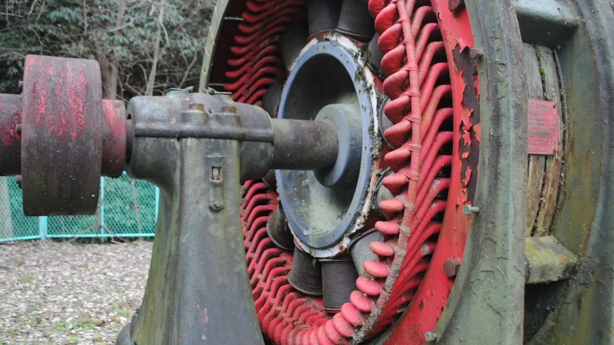
Pop the flywheel cover off almost any UTV and you find a ring of copper coils bolted to the case, sitting a few millimeters from a spinning wheel studded with magnets. That gap is the whole trick behind a charging system. No belts, no brushes, just a magnetic field sweeping past wire thousands of times a minute.
Most owners never think about this until a battery goes flat for the third time in a season. They swap the battery, maybe swap it again, and never ask why the old one kept dying. The answer usually lives inside that cover, in a chain of three parts that most riders can name but few can explain.
This is the plain language version, the one worth reading before you ever pick up a multimeter. Once you know what the stator, rectifier, and regulator actually do, the test numbers in every other UTV Wise guide start to make sense instead of feeling like arbitrary pass or fail lines.
The Flywheel and Magnets Start Everything
The flywheel bolted to the crankshaft carries a ring of magnets, usually rare earth magnets bonded or pressed into the flywheel itself. Depending on the model, you will find anywhere from 6 to 16 magnetic poles arranged around the rim.
As the engine turns, those magnets sweep past the stator without ever touching it. That moving magnetic field is what generates voltage in the windings sitting just behind the flywheel wall. There is no physical contact and nothing to wear down, which is part of why a stator tends to outlast almost everything else on the machine when it is not abused.
The Stator Windings Turn Motion Into Raw AC
The stator itself is a ring of copper wire wound into coils, grouped into legs that electricians call phases. Each phase produces its own alternating current sine wave as the flywheel spins past it.
A healthy stator reads low and even resistance phase to phase, commonly 0.1 to 1.0 ohms depending on the model, with each pair reading close to the others. Phase to ground should read open, essentially infinite resistance. Any continuity between a phase wire and the case means a shorted winding, and that stator is done.
Because voltage generation depends on how fast that magnetic field sweeps past the windings, output and engine speed are directly linked. Idle voltage on a healthy machine often reads only 12.8 to 13.5 volts, which looks low if you do not already know that number is normal. Bring the engine to 3000 rpm and the same system should climb to 13.8 to 14.7 volts. That climbing number is expected, not a fault, which is why every test in this series checks voltage at rpm and not just at idle.
Single Phase Versus Three Phase Stators
Simpler ATVs and older UTVs often use a single phase stator: one winding, one AC output feeding the rectifier. It works fine on a machine whose only real electrical jobs are ignition, lights, and keeping a small battery topped off.
Higher output machines, think Polaris RZR, Can-Am Maverick X3, or a Ranger running a plow and a winch, use a three phase stator instead. Three windings sit 120 degrees apart, so the AC output overlaps and smooths out. After rectification, a three phase system delivers a steadier supply, commonly in the 300 to 600 watt range versus roughly 150 to 250 watts on a basic single phase setup.
That extra capacity is why a three phase machine shrugs off a winch pull and a stereo running at the same time, while a single phase machine loaded with the same accessories tends to run its battery down over a season.
The Rectifier Converts AC Into Usable DC
A battery and the machine electronics run on direct current, not the alternating current a stator produces. The rectifier’s job is to flip the negative half of every AC wave positive, using diodes arranged in a bridge, 4 diodes on a single phase system and 6 on a three phase system.
You can check a diode with a meter set to diode mode. A good silicon diode drops about 0.4 to 0.7 volts in one direction and shows no reading, often displayed as OL, in the other direction. A diode reading the same both ways, or open both ways, has failed.
On almost every modern UTV, the rectifier and the regulator live inside one sealed housing. That is why shops and owners both just call the whole unit the regulator, even though it is doing two separate jobs.
The Regulator Holds Voltage at 13.8 to 14.7 Volts
Raw rectified DC from the stator would climb well past what a 12 volt battery can safely take, especially at higher rpm. The regulator’s job is to hold charging voltage in a tight band, typically 13.8 to 14.7 volts measured at the battery with the engine at 3000 rpm.
Most powersports regulators are shunt style. Instead of throttling the stator directly, they redirect extra current to ground once battery voltage reaches the target, dumping the unused output as heat rather than letting it reach the battery. That is exactly why a regulator bolts to a metal heat sink and can get hot enough to burn skin on a machine that has been running hard.
Safety
Let the engine cool before you touch the regulator, the exhaust, or reach near the flywheel cover. A regulator rectifier can sit well above 150 degrees Fahrenheit after a ride, and a spinning flywheel can injure a hand or catch a loose sleeve in seconds.
Built With Headroom on Purpose
A stator is not sized just to cover what the machine needs to idle and run lights. Engineers build in headroom so the system can recharge the battery after a cold start, run the fuel pump and ignition, and still have capacity left for a winch, aftermarket lights, or a stereo.
A machine that only draws 150 to 200 watts to run down the trail might carry a 400 watt stator specifically so a winch pull does not collapse charging voltage while the engine is also trying to top off the battery.
Here is something techs see constantly on the bench: an owner adds a light bar, a winch, and a stereo over two seasons, one accessory at a time, and never notices a problem until the battery starts dying every weekend. The stator was never the failure. The owner used up the headroom the factory built in, and a marginal ground connection made the shortfall worse.
What Fails Where: Matching Symptoms to the Part
Every symptom you notice on the trail traces back to one of these parts. Knowing the job each one does makes the failure obvious once you see it.
| Part | Job | Symptom When It Fails |
|---|---|---|
| Flywheel magnets | Create the spinning magnetic field | Weakened or cracked magnets give a low, uneven AC output and slow charging |
| Stator windings | Convert motion into raw AC voltage | A shorted winding drains the battery even with the key off; an open winding kills output completely |
| Rectifier diodes | Convert AC into one direction DC | A shorted diode causes overcharge; an open diode cuts output roughly in half |
| Regulator | Holds charging voltage at 13.8 to 14.7 volts | Stuck open lets voltage climb past 15 and can boil the battery; stuck closed starves it below 13 |
| Connector and ground | Carries the signal and the return path | Corrosion or a loose ground reads like a dead stator on a meter but is really a bad connection |
What to Measure Before You Trust Any Guess
Understanding the system is step one. Confirming which part actually failed takes a meter and a short list of checks, in this order.
- Battery voltage rested, no engine running (want 12.6 to 12.8 volts before you blame anything else)
- Charging voltage at idle and again at 3000 rpm (want 13.8 to 14.7 volts at rpm)
- Stator phase to phase resistance, all pairs (commonly 0.1 to 1.0 ohms and close to equal)
- Stator phase to ground resistance (should read open or infinite)
- AC output per phase with the engine running (should rise with rpm into the tens of volts)
- Diode test across the rectifier terminals
- Connector pins for corrosion, melting, or heat discoloration
- Main ground strap for corrosion or a loose bolt
Tip
Warm the engine to normal operating temperature before you read charging voltage. A cold engine idles differently and can shift the reading by close to a volt, enough to make a healthy system look marginal.
Once you can name the part behind a symptom, testing stops feeling like guesswork. A dimming headlight at speed, a battery that only lasts one ride, a regulator too hot to touch, each one points somewhere specific instead of leaving you replacing parts at random.
The next step is putting a meter on the machine. Start with the stator’s two tests, resistance with the key off and AC output with the engine running, since that single component is where most charging failures begin. Compare what you read against the service manual for your exact model, since magnet count and winding design shift the exact numbers from one machine to the next.
Keep the numbers from this guide close by. Once you know that 13.8 to 14.7 volts at 3000 rpm is the target, and that a healthy stator reads low and even resistance with nothing to ground, every test you run afterward has a clear pass or fail line instead of a guess.
Frequently asked questions
What does a UTV stator actually do?
It generates raw alternating current using magnets on the flywheel that sweep past copper windings bolted inside the engine cover. That AC then feeds the rectifier, which converts it into the direct current the battery and electronics use. Output rises with engine speed, often reaching the tens of volts AC by 3000 to 4000 rpm.
What is the difference between a single phase and a three phase stator?
A single phase stator has one winding and one AC output, typically good for about 150 to 250 watts, which suits basic ATVs with light electrical loads. A three phase stator has three windings set 120 degrees apart and commonly delivers 300 to 600 watts, which is why higher output UTVs with winches and stereos use them.
Why does my UTV show low voltage at idle?
Idle voltage of 12.8 to 13.5 volts is normal on most machines because stator output depends on engine speed. Bring the engine to 3000 rpm and a healthy system should climb to 13.8 to 14.7 volts. If it stays near 12.4 volts or lower at that rpm, the charging system is not keeping up.
What is the difference between the rectifier and the regulator?
The rectifier uses diodes to turn AC into DC, while the regulator holds that DC near 13.8 to 14.7 volts by shunting extra current to ground once the battery is topped off. On almost every UTV the two live inside one sealed unit, commonly called the regulator rectifier, even though they do two separate jobs.
Can a stator test fine and the charging system still fail?
Yes. A perfectly good stator can test fine on the bench while a corroded connector, a loose ground strap, or a failed regulator still leaves the battery undercharged or overcharged. Testing stator resistance and AC output first, before replacing parts, saves money on machines that only needed a cleaned connector.

Vidya Verma
Vidya Verma is a UTV and powersports technician with hands-on experience diagnosing electrical, charging, and starting problems on Polaris, Can-Am, and other side-by-side platforms. She writes practical, workshop-tested repair guides that help owners troubleshoot faults, choose the right parts, and get their machines running reliably in the field. When she's not under the hood, she's out riding trails and stress-testing the same fixes she recommends.


